Tuesday, January 29, 2013

How to test a diode
Diodes are one of the components that can be tested very easily.Ordinary diodes as wells as Zener diodes can be checked by using a multimeter. While testing a diode the forward conducting mode and reverse blocking mode has to be tested separately.

Testing ordinary diode using a digital multimeter.
To check an ordinary silicon diode using a digital multimeter, put the multimeter selector switch in the diode check mode. Connect the positive lead of multimeter to the anode and negative lead to cathode of the diode. If multimeter displays a voltage between 0.6 to 0.7, we can assume that the diode is healthy. This is the test for checking the forward conduction mode of diode. The displayed value is actually the potential barrier of the silicon diode and its value ranges from 0.6 to 0.7 volts depending on the temperature.

Now connect the positive lead of multimeter to the cathode and negative lead to the anode. If the multimeter shows an infinite reading (over range), we can assume that the diode is healthy. This is the test for checking the reverse blocking mode of the diode.
For testing Germanium diodes, the procedure is same but the display will be between 0.25 to 0.3 V to indicate a healthy condition in the forward biased mode. The potential barrier for Germanium diode is between 0.25 and 0.3V.When reverse biased the multimeter will show an infinite reading (over range) to indicate healthy condition.
Testing ordinary diode using analog multimeter.
To check an ordinary Silicon diode using an analogue multimeter, put the multimeter selector switch in a low resistance position (say 1K).Connect the positive lead of multimeter to anode of the diode and negative lead of multimeter to cathode of the diode. If meter shows a low resistance reading, we can assume that the diode is healthy. This is the test for checking forward biased mode of the diode.

Now put the multimeter selector switch in a high resistance position (say 100K).Connect the positive lead of multimeter to cathode of the diode and negative lead to anode of the diode. If the meter shows an infinite reading, we can assume that the diode is healthy. This is the test for checking the reverse blocking mode of the diode. The meter shows infinite or very high resistance reading because a reverse biased diode has a very high resistance (usually in the range of hundreds of K Ohms).
Testing Zener diode.
The forward characteristics of a Zener diode is similar to an ordinary diode.So the methods used for testing forward conducting mode of any ordinary diode is applicable to the Zener diode too.But in reverse mode, the reverse breakdown voltage has great significance and it has to be specifically tested.For example a 5.3V Zener diode must start conducting only when the applied reverse voltage just exceeds 5.3V.The reverse bias mode of Zener diode can be easily tested by using the circuit given below.The resistance R1 can be typically 100Ohms.The multimeter must be in voltage mode.Now slowly increase the output of variable power supply and at the same time observe the voltage shown in the multimeter. The multimeter display increases along with the increase in power supply voltage until the breakdown voltage. Beyond that the multimeter reading stays put despite of the power supply voltage. This is because the Zener diode is now in breakdown region and the voltage across it will remain constant irrespective of the increase in supply voltage and this constant voltage will be equal to the breakdown voltage. If the reading of multimeter in this instant is equal to the breakdown voltage specified by the manufacturer, we can assume that the Zener diode is healthy.
While carrying out this test, remember not to exceed the input excitation voltage to a point that forces the Zener diode to dissipate more power than it can safely handle. Typically current through the diode should not be allowed to exceed more than 10mA.


How To Check Capacitor - Electronic Repair
Read On To Learn How To Check A Capacitor
If you want to know if a capacitor is defective or not then you need to know how to check capacitors using a multimeter, in this lens you will learn the correct way to do this and the equipment you will need to do the job.
Equipment Needed To Check Capacitor
To perform a check on a capacitor whilst it is still in circuit you will need an ESR meter or if you are planning on removing the capacitor from the circuit then you can get away with just using a multi-meter as an ohm-meter to test the capacitor.

To find out if your capacitor is running at the correct micro farad then you will need to purchase a capacitor tester.

What You Need To Do To Check A Capacitor Assuming that you have already removed the capacitor from the circuit board you then need to make sure that the capacitor has been discharged as they carry a charge, the easiest way to do this on a relatively small capacitor is to use a 12v automotive bulb and touch the ground of the capacitor to the case of the bulb and the power pin to the contact point of the bulb, this will dissipate the charge and then you can safely check the capacitor with your multimeter.

To use a capacitor tester you need to select the correct micro-farad setting to use, if your capacitor says 680 micro-farad then set the tester to the higher range usually 2000 mf, once you have done this just attach the black probe lead to the ground on the capacitor and the red probe to the power, you should then get a reading of the exact micro-farad which you can compare to what is written on the side of the capacitor. Don't worry i have provided some useful videos further down the page to make it abit clearer for you.

To use a multimeter
To use a multimeter to check your capacitor is working effectively you need to set the meter to the high ranges 10k - 1m and connect the probes in the same way as the capacitor tester, black to ground red to power, as soon as the probes make contact the meter should swing near zero then slowly move toward infinity before coming to a rest at infinite ohms as the capacitor is being charged by the battery in the multimeter. If the capacitor is bad then the meter will go to zero ohms and remain there, if this is the case then this is known as a shortened capacitor.
In the case of an open capacitor there will be no ohm reading and some capacitors have a dielectric leakage, you will know this if the ohm-meter comes to a rest at a point before infinity but please check this against a known working capacitor.


what do you set the multimeter
In most cases you CAN'T use a multimeter to test a capacitor. At least, you can't measure the cap's value, but you can tell if the cap has a short.

A GOOD CAPACITOR will measure a very HIGH resistance on ALL ranges.

However, if the capacitor is SHORTED (a common problem) then the OHMETER function can be used to check it.

If the capacitor is SHORTED then the ohmeter will read 0 (zero) ohms.

It is also possible for a capacitor to have a HIGH RESISTANCE short. So check the capacitor using several different ohmeter ranges. A high resistance short will measure open ciruit on the low ohm ranges, and medium resistance on the high ohm ranges.

Very high value capacitor (like 100,000 uF) will show interesting results. When the ohmeter is first attached they will show zero ohms, but then the meter will slowly climb up to very high resistence readings. This is normal for very high capacitance values.

BTW: Watch the polarity on electrolytic caps. Always connect + to + and - to -

Other than the above, you need a special Capacitance Check Meter.

Tuesday, January 22, 2013

How to handle an AC adapter properly
Please note: Never use the AC adapter if it shows any signs of damage. When removing the AC adapter from the computer never pull from the cord, always grasp the connector and gently pull the cord from the computer.
Issues caused by handling the AC adaptor other then recommended may not be covered under warranty.
Always wrap the cord as shown when transporting or storing your AC adaptor.

Do not wrap the power cord around the AC adaptor as this can cause the wires to split or snap where it enters the AC adaptor (see below).
Do not allow the AC adaptor to hang from the computer (as pictured below) as this can cause the DC Jack on the computer to break.
Do not put any pressure on the AC adaptor connector or the DC Jack as this can damage the AC adaptor or the computer or both.
Did you find this helpful?
How To Create a Windows 7 Logon Password
When you start your computer, does Windows 7 ask for a password? It should. If not, you need to create a password as soon as possible.
Not having a Windows 7 password is a big security concern. Without a password, anyone in your home or office has full and unrestricted access to everything on the computer. Fortunately, creating a new Windows 7 password is very simple.
Follow the steps below to create a password for your Windows 7 logon account:
Note: If you're trying to create a new Windows 7 password because you've forgotten yours and can't get in to Windows, see Tip #2 at the bottom of the page for help.
Difficulty: Easy
Time Required: Creating a Windows 7 password usually takes less than a few minutes
Here's How:
Click on Start and then Control Panel.
Click on the User Accounts and Family Safety link.
Note: If you're viewing the Large icons or Small icons view of Control Panel, you won't see this link. Simply click on the User Accounts icon and proceed to Step 4.
Click on the User Accounts link.
In the Make changes to your user account area of the User Accounts window, click the Create a password for your account link.
In the first two text boxes, enter the password you would like to start using.
Entering the password twice helps to make sure that you typed your new password correctly.
In the final text box, you're asked to Type a password hint.
This step is optional but I highly recommend that you use it. If you try logging in to Windows 7 but enter the wrong password, this hint will pop up, hopefully jogging your memory.
Click the Create password button to confirm your new password.
You can now close the User Accounts window.
Now that your Windows 7 account has a password setup, you must use this password to log on to Windows 7 from this point forward.
Create a Windows 7 password reset disk. While not a required part of creating a new password, I highly recommend that you do this.
A password reset disk will protect you from the consequences of forgetting your new Windows 7 password.
Tips:
1.Not a Windows 7 user? See How Do I Create a Password in Windows? for specific instructions for your version of Windows.
2.If you need a new Windows 7 password because you've forgotten yours and can no longer access Windows, then you obviously can't use the method above.
You can, however, use a free Windows password recovery program to crack or reset the password even if you can't get in to Windows 7 at all. You can then create a new Windows 7 password using the instructions above.

Thursday, January 17, 2013

My kyocera km-2550 multifunctional copier has

My kyocera km-2550 multifunctional copier has started showing a error message "call for service c6000" and a phone number in asterisks. kindly advice on what to do or if there any online help.
This is fuser unit error code, you can try to reset it might work, but if the erorr code came back then you need to change the fuser unit.

In order to reset this code: follow those steps
on the panel press 1087 1087
The screen will change to service mode
on the panel again press 163
now look at the screen and you will see Excute.
Select Excute and press the Start key.
The Machine will rebot or it will asks you to turn it off and on.
After the machine load again, it should be good, if the Error came back!! Then change the Fuser Unit.
How to Connect a Wireless Mouse
A wireless mouse can make your desk look a more modern and neat by eliminating cords. It can also make using the mouse more comfortable for you. If you've never worked with wireless accessories before, setting up a wireless mouse might seem a little complicated. Some wireless mice use USB receivers, and others use Bluetooth. We'll show you how to connect either one.
connecting to a Receiver
1.Insert the batteries into the mouse. Turn the mouse over, find the battery cover, and slide it off. Insert the appropriate batteries—usually two AAs.

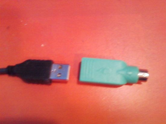
2.Connect the receiver to the computer. If your computer has a USB port (as most do), plug your receiver into an available port. There will also be a green adapter supplied, in the event that your system requires the use of the mouse port. Caution—don't try and force the mouse adapter into the keyboard port!

The mouse receiver has a USB plug (left), but can also plug into the mouse plug through the adapter it came with (right). If your receiver plugs into the USB port it should look like the left. If it plugs into the mouse plug it should look like the one on the right, only connected to the receiver.
3.Connect the mouse to the receiver. Place the mouse in close proximity to the receiver, and note the following:
The receiver should have a visible button that is easily pushable by the average human finger.
The mouse will usually have a very small reset button in a hole on the bottom that can be pushed by something like a pencil or paper clip.
Push both buttons at the same time with the receiver and the mouse relatively close to each other for about 5 seconds or more.
4.Find a permanent position the receiver. Place the receiver where it won't be far away from the mouse. Depending on where you are, you can place it on the monitor, on the tower, on the back of your laptop (if you are installing the mouse to your laptop) or on the desk.
The furthest a wireless mouse can get away from the receiver and still function is about 9 feet (2.7 meters), so keep that in mind.
5.Test your new mouse.
If you plugged into the mouse port, restart your computer.
If you plugged it into the USB port you should be able to use it immediately.
When the cursor moves when you move the mouse, you have connected the mouse properly. If the cursor doesn't move, try repositioning the receiver. If it still doesn't work, you may need to restart your computer (if you haven't already) or reconnect everything.
6.Adjust your mouse settings. Use the control panel that came with your wireless mouse, or download the necessary software from the manufacturer's website. Adjust the settings so that the mouse performs as you require.

Connecting Via Bluetooth
1.Insert batteries into your mouse. Turn your mouse over, locate the battery cover, and remove it. Insert the appropriate batteries—usually two AAs
2.Enable Bluetooth. In your Bluetooth control panel, make sure Bluetooth is turned on, and that your device is discoverable. (Refer to the device's user's guide for more information.)
Usually, the status LED on the mouse will blink when it's discoverable.
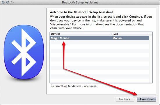
3.Discover the mouse. Set your Bluetooth setup control panel to discovery mode. It will search for available Bluetooth signals, then notify you when your mouse has been found.

Once the mouse has been discovered, follow the on-screen steps to finalize you setup procedure.
4.Adjust your mouse settings. Use the control panel that came with your wireless mouse, or download the necessary software from the manufacturer's website. Adjust the settings so that the mouse performs as you require.

Monday, January 14, 2013

How to read color codes from resistors.


The value of the resistor is marked on the body using colors. Every color is different number and you can remember these numbers or you can just use the table on next step. OR there are much resistor calculators that you can use. It's for the laziest people :D . However it's your decision ,and I will show you all ways to calculate resistor value.

Colors

Here is the table with the colors and numbers. As you can see they are:
BLACK: 0
BROWN: 1
RED: 2
ORANGE: 3
YELLOW: 4
GREEN: 5
BLUE: 6
VIOLET: 7
GREY: 8
WHITE: 9
But this is not for all colors. From right to left the second color is multiplier. Digits from the first colors must be multiplied with the number of this color.
BLACK: 1
BROWN: 10
RED: 100
ORANGE: 1000
YELLOW: 10000
GREEN: 100000
BLUE: 1000000
GOLD: 0.1
SILVER: 0.01
And the last color: This is tolerance. Tolerance is the precision of the resistor and it is given as a percentage. For example a 390 resistor with a tolerance of ±10% will have a value within 10% of 390, between 390 - 39 = 351 and 390 + 39 = 429 (39 is 10% of 390).
BROWN: 1%
RED: 2%
GOLD: 5%
SILVER: 10%
NOTHING: 20%

Calculator

Resistor color code calculator
If you are too lazy to think about colors and digits and mat ... this is for you :) :D

Examples

Exemple: If first color is RED ,second is RED ,third is BLACK and the last is SILVER it means:
RED - 2 -- RED - 2 -- YELLOW - x10000 -- SILVER - 10% so...
2 2 0000 +/- 10% * 2 2 0000 so... :D
220000 +/- 22000
This is 220 000 Ohm or 220 kOhm
or 220 000 - 22 000 Ohm or 220 - 22 kOhm
or 220 000 + 22 000 Ohm or 220 + 22 kOhm